Note that the Arlo Robot System is discontinued.
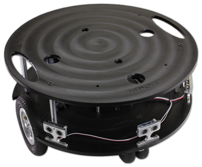
The Arlo Robot is a very versatile mobile robotic system. Arlo is robust, easily expandable, and provides a solid platform for autonomous robotic research and development applications. The platform is rated for up to 35 pounds of payload (that’s in addition to the Arlo Robot’s own weight).
This Assembly Guide will lead you step-by-step through the entire Arlo build process. From the drive motor/encoder systems, to the assembly of the Arlo Power Distribution Board, through the wiring and electrical connections, and finally to the installation and sample programming of the Propeller Activity Board WX (#32912) – which acts as Arlo’s primary controller.
Going through the build process will provide you with a clear understanding of not only how the Arlo system physically goes together, but also how the independent components connect and interact with the sample code that we’ll provide. From then on – it’s up to you!
Although the Arlo Complete Robot System may seem to go together in a straight-forward manner, it is best to follow the assembly sequence (outlined in this guide) which may prevent you from having to do some back-up work.
Scope:
This guide consists of 8 discrete physical assembly sections, starting with the Motor-Mount and Wheel Kit and ending with the installation of the control board. You will also be directed to follow a separate guide outlining electrical connections and test code for the control board you will be using (Activity Board WX – included, or BASIC Stamp Board of Education/Board of Education Shield + Arduino – not inlcuded). From that point on, you’re free to expand Arlo’s capability to wherever you want it to go.
Preparation:
- Do not open each sub-assembly kit until it’s time for that particular device to be assembled. The last thing you want is to have to figure out what screws go with which sub-assembly!
- Although the assembly of the Arlo Robot is a straight-forward and relatively safe process, you will be using tools that, if used incorrectly, can lead to inadvertent damage to your Arlo robotic system or yourself. As an example, the installation and subsequent mounting of the encoder wheel and delicate sensor assembly should be done with patience and precision to avoid potential damage to these components.
- Keep in mind there are small components– some very small (screws notably) that can be easily lost in a disorganized “work zone”. We recommend a dedicated table and work area with perhaps an old bed-sheet or large piece of cardboard as the work surface. A setup like this will provide an organized and clean assembly area as well as a scratch– and damage-proof work area.
- Read through the entire assembly and testing process for each Section before you start. If you go slow and follow these instructions, you should experience few – if any – issues with the assembly of your Arlo robotic system.
Should the need arise, Parallax provides free tech support – either through our Forums (forums.parallax.com), by email (support@parallax.com), or you can call our tech support department directly at (888)-512-1024. For missing parts, or other questions relating to your sales order, contact our sales department: 888-512-1024 within USA / 916-624-8333 outside of US, or email to sales@parallax.com.
Build Sequence:
The mechanical build process is divided into 8 sections:
- Section 1: Motor Mount and Wheel Kit Assembly
- Section 2: Caster Wheel Kits
- Section 3: Mounting Wheel Assemblies
- Section 4: Arlo Power Distribution Board
- Section 5: Batteries and Battery Tray
- Section 6: Assembling and Mounting the Ping))) Sensors
- Section 7: Control Components and the DHB-10 Connections
- Section 8: Arlo Top Deck
