Get Ready to Build
Building and controlling circuits with the Propeller microcontroller is a great way to learn about electricity, and to experiment with making your own inventions. Building experimental circuits to design your own projects is called prototyping, and it is a real-world engineering skill. Before you start your Propeller prototyping, there are three important Reference pages you should have handy, especially if you have never built circuits on a breadboard before. Just click on each link at the page will open in a new tab or window.
- Open the Breadboard Basics page, and watch the video if you can.
- Open the Schematic Symbols page, and look up the symbols for Resistor, Light-Emitting Diode, and Microcontroller Output Pin.
- Open the Resistor Color Codes page (we’ll use it soon).
- Now, scroll down to about the the prototyping area you are using:
- the Breadboard on the Propeller Activity Board, or
- the Propeller FLiP Module on a breadboard.
The Breadboard on the Propeller Activity Board
Propeller Activity Board WX Product Guide
The Propeller Activity Board has a breadboard mounted on it. Here, you can build your own circuits with common electronic components. (It also has lots of pre-built circuits for using a speaker, SD card, wireless RF module; read all about them in the Product Guide if you like, but they won’t be used in the Circuit Practice tutorial.
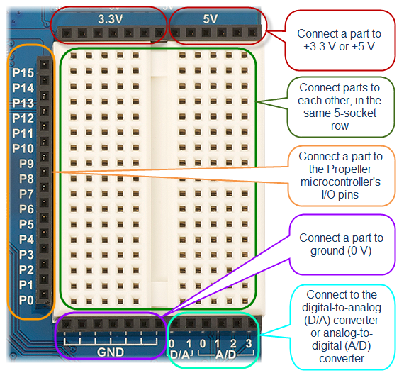
The Propeller Activity Board’s breadboard is surrounded on three sides by black sockets. These make it convenient to connect circuits on the breadboard to power, ground, and the Propeller I/O pins. There are also sockets to connect to a digital-to-analog converter and an analog-to-digital converter.
The 3-Position Power Switch
You had to set this switch to position 1 for the Hello World program, and to blink its built-in LEDs. Now, let’s see how to use it when building circuits.
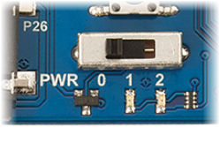
- Position 0 turns off power to the board. Always set the switch to Position 0 before building or modifying circuits. (You may still see lights blinking by the USB port if it is plugged in.)
- Position 1 connects power to the Propeller system and the black sockets along the three edges of the white breadboard. It does NOT connect power to the 3-pin servo ports labeled P12-P17 that are above the white breadboard. Position 1 is fine if you are not using the servo ports for anything. However, if you are building a robot, put the switch in Position 1 and then load the program into EEPROM. Then, put the switch in Position 2 to drive. This will keep the robot from driving off the table as soon as the program is loaded.
- Position 2 powers all the circuits on the board, including the 3-pin servo ports. Put the switch in Position 2 when you are ready to power the servo ports.
The Propeller FLiP Module on a Breadboard
Propeller FLiP Module Product Guide
The Propeller FLiP module is designed to plug right into a standard breadboard, where you can connect it to other circuits that you build. You can connect to any of its pins by inserting a wire or component lead into the same 5-socket row. Be sure to check each pin label on the board before making a connection. To learn more about what each pin does, see the Product Guide linked above.)
The FLiP Module’s breadboard is made of several sections: two wider prototyping areas with 5-socket rows in two columns, and three narrow power rails with one long row for postitive connections and the other for ground. You use jumper wires to connect the power rails to power and ground connections on the Propeller FLiP module.
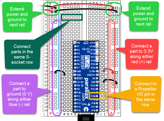
The Circuit Practice tutorial examples can all use power supplied by your computer’s USB port. Most of the circuits will access 3.3V through the Propeller I/O pin connections. Some circuits will need to get power through Propeller FLiP module’s 3.3V► pin. And all circuits will need a connection to ground.
- Use black jumper wires to connect two of the Propeller FLiP module’s GND pins to blue ground (-) rails, one on each side of the module.
- Use a red jumper wire to connect the Propeller FLiP module’s 3.3V► pin to a red power (+) rail.
- Use two more black jumper wires to connect all three blue ground (-) rails together.
- Use two more red jumper wires to connect all three red power (+) rails together.
Not every circuit needs every connection shown above. Each example circuit will have a wiring diagram to show which connections are necessary.
Powering your FLiP Module
Since your Propeller FLiP module is powered through the USB port, you will need to unplug the USB cable to disconnect power. Always disconnect power before building or modifying circuits. To reset the Propeller chip to run a program over again, you only need to push the Reset button; you do not need to disconnect power just to reset.