Build the IR Sensor Circuits
In this activity, you will build and test the infrared object sensors to make sure they detect objects in front of the ActivityBot.
Circuit
Parts Required
(2) IR LEDs
(2) IR receivers
(2) 1 k-ohm resistors (brown-black-red)
(2) 220-ohm resistors (red-red-brown)
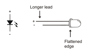
- Find the two IR LEDs in your kit — they are the clear ones with dome-shaped (not flat) tops.

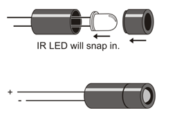
To direct the IR LED’s light, just like a flashlight beam, we’ll use an IR LED standoff (longer tube) and shield (shorter tube).

- Insert the IR LED’s leads into the standoff tube, and out through the two holes at the bottom of the standoff.
- Press firmly and the IR LED should snap into place. If it doesn’t, pull it out, give it a half turn, and try again.
- Fit the LED shield onto the standoff.
Although the shield friction-fits into the standoff, it can be helpful to place a small piece of clear tape around the tube where they meet to hold them together securely. Make sure the tape does not extend beyond the end of the tube or cover the IR LED.
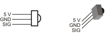
- Find the IR receivers in your kit. If you have two different kinds, use the ones with the silver metal cases for this activity.


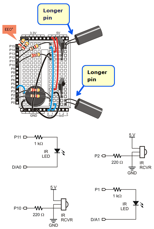
The IR LED’s cathodes are connected to D/A0 and D/A1. For object detection, the D/A outputs are set to 0 V = GND. Their voltage can be increased to make the IR LEDs dimmer, for closer range detection. (They can even be tested at different voltages—levels of dimness—to get a rough idea of the object’s distance, but that’s for another activity…)
- Use this wiring diagram and schematic to build the infrared detectors.
- Make sure the longer IR LED anode pins are plugged into the rows shown in the wiring diagram.
- Make sure your IR receivers are the silver ones with metal cases (not the black plastic ones).
- Ignore the 20k resistors connecting P14 & P15 to the 3.3V header, if your kit is using the Feedback 360 servos with the yellow signal wire.

*P14/P15 resistors are only needed for ActivityBot kits using External Encoders (#32500).
