Activity 3: Light Measurements for Roaming
We now have circuits that can work under a variety of lighting conditions. Now we need some code that can adapt as well. An example of sketch code that cannot adapt to change would be:
if(tLeft > 2500)… // Not good for navigation.
Maybe that statement would work well for turning away from shadows in one room, but take it to another with brighter lights, and it might never detect a shadow. Or, take it to a darker room, and it might think it’s seeing shadows all the time. For navigation, what matters is not an actual number reporting the light level over each sensor. What matters is the difference in how much light the two sensors detect, so the robot can turn toward the sensor seeing brighter light (or away from it, depending on what you want.)
The solution is simple. Just divide the right sensor measurement into the sum of both. Your result will always be in the 0 to 1 range. This technique is an example of a normalized differential measurement. Here’s what it looks like as an equation:
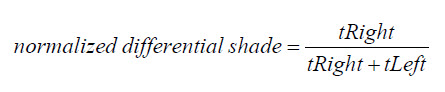
For example, a normalized differential measurement of 0.25 would mean “the light is 1/2 as bright over the right sensor as it is over the left.” The actual values for tRight and tLeft might be small in a bright room or large in a dark room, but the answer will still be 0.25 if the light is 1/2 as bright over the right sensor. A measurement of 0.5 would mean that the tRight and tLeft values are equal. They could both be large, or both be small, but if the result is 0.5, it means the sensors are detecting the same level of brightness.
Here’s another trick: subtract 0.5 from the normalized differential shade measurement. That way, the results range from –0.5 to +0.5 instead of 0 to 1, and a measurement of 0 means equal brightness. The result is a zero-justified normalized differential shade measurement.
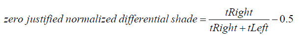
But why do it? The value range –0.5 to +0.5 is great for navigation sketches because the positive and negative values can be used to scale the wheels speeds. Here is how the zero-justified normalized differential shade equation appears in the next sketch:
  float ndShade;                             // Normalized differential shade
  ndShade = tRight / (tLeft + tRight) - 0.5; // Calculate it and subtract 0.5
The final measurement will be stored in a floating point variable named ndShade, so that gets declared first. Then, the next line does the zero-justified normalized differential shade math. The result will be a value in the –0.5 to +0.5 range that represents the fraction of total shade that tRight detects, compared to tLeft. When ndShade is 0, it means tRight and tLeft are the same values, so the sensors are detecting equally bright light. The closer ndShade gets to –0.5, the darker the shade over the right sensor. The closer ndShade gets to 0.5 the darker the shade over the left sensor. This will be very useful for navigation. Let’s test it first with the Serial Monitor.
Example Sketch: LightSensorValues
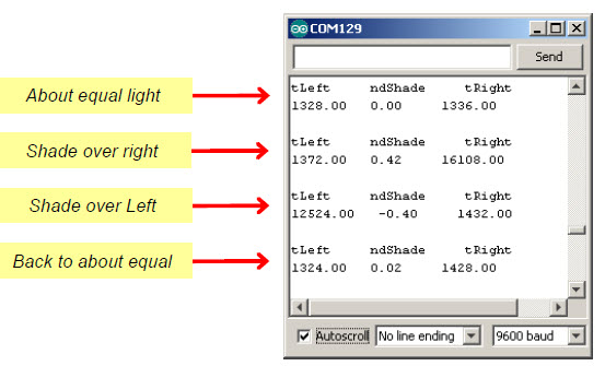
This screencapture shows a Serial Monitor example with the LightSensorValues sketch running. With shade over the right sensor, the ndShade value is about 0.4. With shade over the left sensor, it’s about –0.4.
- Make sure there is no direct sunlight streaming in nearby windows. Indoor lighting is good, but direct sunlight will still flood the sensors.
- Verify that when you cast shade over the BOE Shield-Bot’s left sensor, it results in negative values, with darker shade resulting in larger negative values.
- Verify that when you cast shade over the BOE Shield-Bot’s right sensor, it results in positive values, with darker shade resulting in larger positive values.
- Verify that when both sensors see about the same level of light or shade, that ndShade reports values close to 0.
- Try casting equal shade over both sensors. Even though the overall light level dropped, the value of ndShade should still stay close to zero.
/*
 * Robotics with the BOE Shield - LightSensorValues
 * Displays tLeft, ndShade and tRight in the Serial Monitor.
 */

void setup()                                 // Built-in initialization block
{
  tone(4, 3000, 1000);                       // Play tone for 1 second
  delay(1000);                               // Delay to finish tone

  Serial.begin(9600);                        // Set data rate to 9600 bps
}

void loop()                                  // Main loop auto-repeats
{
  float tLeft = float(rcTime(8));            // Get left light & make float
  float tRight = float(rcTime(6));           // Get right light & make float

  float ndShade;                             // Normalized differential shade
  ndShade = tRight / (tLeft + tRight) - 0.5; // Calculate it and subtract 0.5

  // Display heading
  Serial.println("tLeft     ndShade     tRight");

  Serial.print(tLeft);                       // Display tLeft value
  Serial.print("   ");                       // Display spaces
  Serial.print(ndShade);                     // Display ndShade value
  Serial.print("     ");                     // Display more spaces
  Serial.println(tRight);                    // Display tRight value
  Serial.println(' ');                       // Add an extra newline

  delay(1000);                                // 1 second delay
}

long rcTime(int pin)                         // rcTime measures decay at pin
{
  pinMode(pin, OUTPUT);                      // Charge capacitor
  digitalWrite(pin, HIGH);                   // ..by setting pin ouput-high
  delay(5);                                  // ..for 5 ms
  pinMode(pin, INPUT);                       // Set pin to input
  digitalWrite(pin, LOW);                    // ..with no pullup
  long time  = micros();                     // Mark the time
  while(digitalRead(pin));                   // Wait for voltage < threshold
  time = micros() - time;                    // Calculate decay time
  return time;                               // Returns decay time
}